Phase Contrast Imaging
Introduction
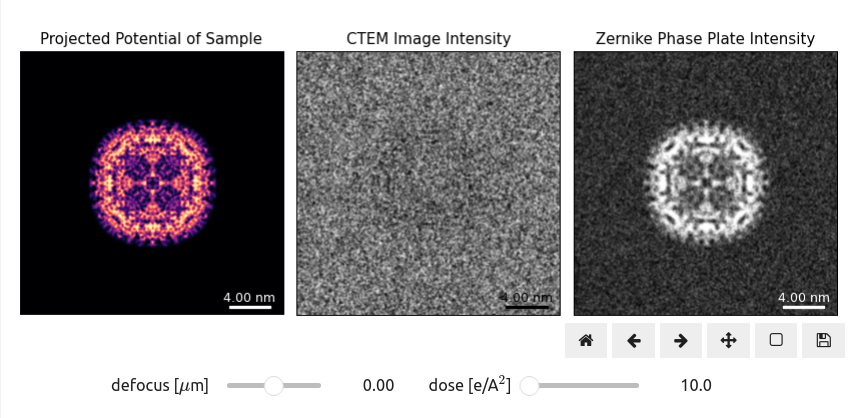
One of the most powerful operating modes for transmission electron microscopy (TEM) is phase contrast imaging (PCI) where imaging optics or detector configurations are used to convert phase modulations of the electron beam into intensity variations Carter & Williams, 2016. The simplest method to produce phase contrast in plane wave TEM imaging is to apply under- or over-focus to the electron wave after it interacts with the sample, shown in Figure 1. The protein sample shown here is apoferritin, which produces very weak diffraction of the electron beam. To produce usable contrast from defocus, we must either apply a large defocus or increase the electron fluence, colloquially referred to as the electron dose Egerton, 2021.
Conventional TEM experiments cannot directly measure phase. Our detectors measure only the intensity (squared amplitude) of the electron wavefunction
Imaging with Defocus
Defocusing an electron wavefunction by a distance to produce the output wave can be modeled mathematically using the expression
where λ is the (relativistically-corrected) electron wavelength, is the imaginary constant, and is the 2D convolution operator. This expression is not practical for numerical calculations, and so we use the convolution theorem to defocus the wave using 2D fast Fourier transforms (FFT), given by the expression
where is the 2D Fast Fourier transform between the real space coordinates and Fourier space coordinates . The electron wavefunction after interacting with a weakly-scattering sample can be approximated as
where the is the phase shift imparted by the sample, and it is considered to be a weak phase object Vulović et al., 2014. Combining equations (3) and (4), we can derive the measured intensity for a weak phase object to be
Imaging with a Phase Plate
An alternative PCI method for plane wave TEM is to use a post-specimen phase plate which advances the phase of the unscattered zero beam with respect to the scattered electrons, or vice versa. These phase plates have various designs, including a Zernike phase plate Zernike, 1942, Boersch phase plate Boersch, 1947, Volta phase plate Danev et al., 2014, or the recently developed laser phase plates Schwartz et al., 2017. An ideal phase plate can be modeled in diffraction space using the expression
where is the Delta Dirac function. Figure 1 shows how (idealized) phase plate PCI compares to defocusing the sample. The sample intensity for a weak phase object is given by the expression
We note however that practical implementations of phase plates remaining challenging, and typically do not perform as well as the ideal case shown above Nagayama, 2011.
- Carter, C. B., & Williams, D. B. (2016). Transmission electron microscopy: Diffraction, imaging, and spectrometry. Springer. https://doi.org/10.1007/978-3-319-26651-0
- Egerton, R. (2021). Dose measurement in the TEM and STEM. Ultramicroscopy, 229, 113363. https://doi.org/10.1016/j.ultramic.2021.113363
- Vulović, M., Voortman, L. M., van Vliet, L. J., & Rieger, B. (2014). When to use the projection assumption and the weak-phase object approximation in phase contrast cryo-EM. Ultramicroscopy, 136, 61–66. https://doi.org/10.1016/j.ultramic.2013.08.002
- Zernike, F. (1942). Phase contrast, a new method for the microscopic observation of transparent objects. Physica, 9(7), 686–698. https://doi.org/10.1016/S0031-8914(42)80079-8
- Boersch, H. (1947). Über die kontraste von atomen im elektronenmikroskop. Zeitschrift Für Naturforschung A, 2(11–12), 615–633. https://doi.org/10.1515/zna-1947-11-1204
- Danev, R., Buijsse, B., Khoshouei, M., Plitzko, J. M., & Baumeister, W. (2014). Volta potential phase plate for in-focus phase contrast transmission electron microscopy. Proceedings of the National Academy of Sciences, 111(44), 15635–15640. https://doi.org/10.1073/pnas.1418377111
- Schwartz, O., Axelrod, J., Tuthill, D., Haslinger, P., Ophus, C., Glaeser, R., & Müller, H. (2017). Near-concentric Fabry-Pérot cavity for continuous-wave laser control of electron waves. Optics Express, 25(13), 14453–14462. https://doi.org/10.1364/OE.25.014453
- Nagayama, K. (2011). Another 60 years in electron microscopy: development of phase-plate electron microscopy and biological applications. Journal of Electron Microscopy, 60(suppl_1), S43–S62. https://doi.org/10.1093/jmicro/dfr037


